M-211 CFD
Water Flow Through an Elbow
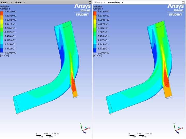
A Computational Fluid Dynamics project comparing water flow through two elbow geometries with two velocity inlets and one pressure outlet. Using ANSYS Fluent, the study evaluated how increasing the smaller inlet diameter affected internal velocity, pressure, temperature distribution, and flow pathlines.
Geometry Comparison
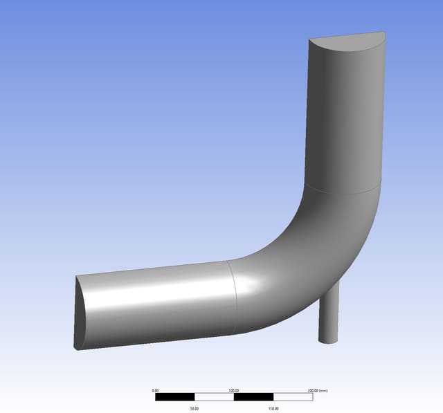
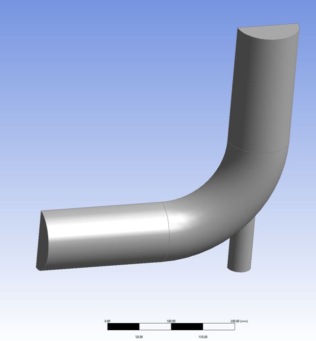
Compared two multi-inlet elbow models with a 100 mm primary inlet and 100 mm outlet. The smaller inlet diameter increased from 25 mm in the original elbow to 38 mm in the revised geometry.
Flow Conditions
Modeled liquid water entering the 100 mm inlet at 0.4 m/s and 293.15 K, with a secondary inlet velocity of 1.2 m/s and a temperature of 313.15 K; both models used a pressure outlet.
CFD Method
Used the k-omega SST turbulence model with second-order discretization methods. The elbow and revised-elbow meshes contained approximately 119,161 and 117,156 cells, respectively.
Analysis
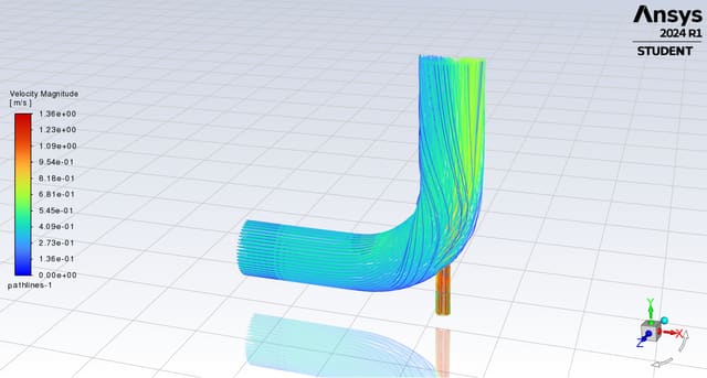
Evaluated solution residuals, outlet temperature profiles, velocity-magnitude contours, pressure fields, and pathlines to visualize mixing and flow behavior through both configurations.
Compare Before / after
Original vs. revised elbow geometry
Water Flow Through an Elbow
Photos & figures
1 / 7
-
Original elbow geometry with 100 mm primary inlet, 25 mm secondary inlet, and 100 mm outlet.
-
Revised elbow geometry with the secondary inlet increased to 38 mm.
-
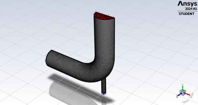
Computational mesh for the original elbow configuration.
-
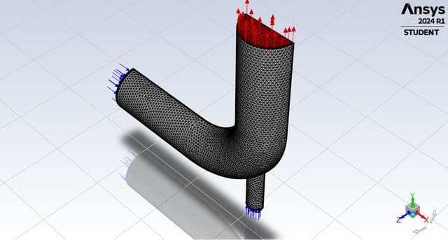
Computational mesh for the revised elbow configuration.
-
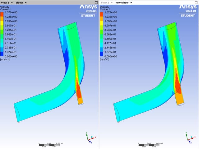
Velocity-magnitude result used to examine internal flow behavior.
-
Pressure-field result for the elbow flow analysis.
-
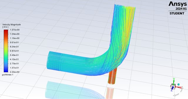
Velocity-magnitude pathlines showing water flow through the revised elbow.