M-208 CFD
Subsonic Wind Tunnel Optimization
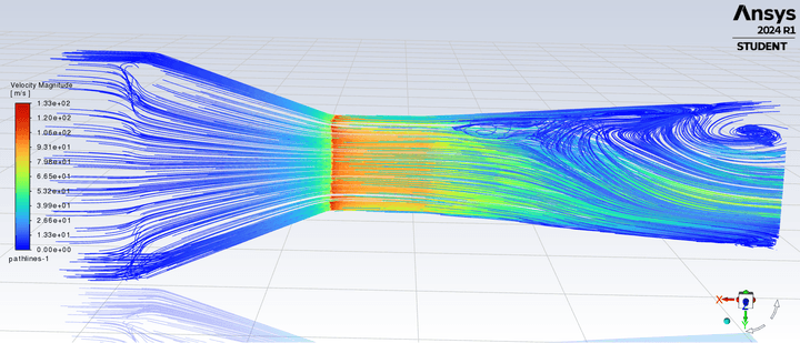
A Computational Fluid Dynamics project focused on improving a homemade, open-system subsonic wind tunnel for small-scale aerodynamic testing. I led the ANSYS Fluent modeling and diffuser-optimization work, evaluating geometry changes that could reduce recirculation and improve test-section flow quality.
My Role
Led diffuser analysis in ANSYS Fluent, created the base and modified geometries, completed mesh-independence verification, and produced velocity-vector and pathline visualizations.
Method
Compared 46 × 46 mm, 40 × 40 mm, and 36 × 36 mm diffuser outlets using turbulent-flow simulations, mesh analysis, residual monitoring, and velocity-based flow visualization.
Key Result
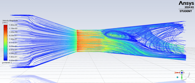
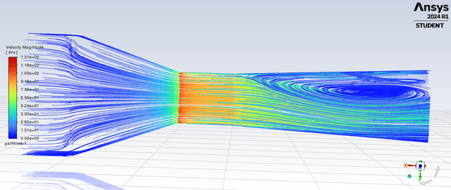
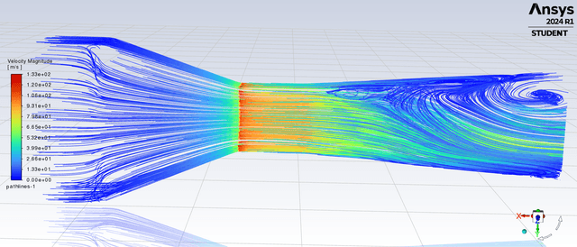
Reducing the diffuser angle from 12.95 degrees to 10.20 degrees substantially reduced the recirculation zone downstream of the test section.
Deliverable
A formal CFD report documenting geometry development, simulation settings, mesh verification, flow results, and recommended design improvements.
Compare Before / after
Diffuser outlet: 46 × 46 mm vs. 36 × 36 mm
Subsonic Wind Tunnel Optimization
Photos & figures
1 / 6
-
Velocity-magnitude pathlines: 46 × 46 mm diffuser outlet.
-
Velocity-magnitude pathlines: 40 × 40 mm diffuser outlet.
-
Velocity-magnitude pathlines: 36 × 36 mm diffuser outlet.
-
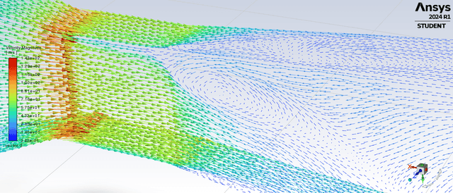
Velocity-magnitude vectors: 46 × 46 mm diffuser outlet.
-
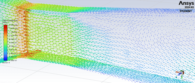
Velocity-magnitude vectors: 40 × 40 mm diffuser outlet.
-
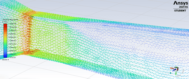
Velocity-magnitude vectors: 36 × 36 mm diffuser outlet.